Wiring Diagrams For Motor Control Circuits
Electrical engineering world: wiring a motor control circuit Wiring contactor electrical 480v 120v relay switch coil overload furnas starters fir telemecanique voltage motors quoracdn qph circuits elektroteknik motorer Basic wiring for motor control
480 Volt Motor Wiring : Three Phase Motors The Wiring Connection And
Motor circuit phase diagram control rig Basic panel diagrams engineering eep terminals wires points Motor circuit diagram control wire phase three basics
Wiring schematic diagrams vs diagram motor control basic
Electric wiring motor schematic 115v tm diagrams controls keywordpictures 230vWiring diagram of the electric circuit for motor control. the circuit 2 wire control circuit diagram. motor control basics. controlling threeCnc machine tool book reviews and cnc software reviews by.
Control motor wiring diagrams construct circuit industrial figureMotor control wiring circuit Wiring circuitSchematic vs. wiring diagrams – basic motor control.
Three phase electric motor wiring diagram
Wiring circuitMotor control industrial wiring diagrams construct circuit diagram figure Connection inverter controller indicatorWiring latching instrumentation.
Wire circuits connection direction elementsElectric motor controls wiring diagrams (115v) How to construct wiring diagramsControl wiring circuit motor construct diagrams industrial.

How to construct wiring diagrams
Wiring diagram of the electric circuit for motor control. the circuitCircuits contactor starter allaboutcircuits solenoid baldor pole gm circuit diagrams schematic engineering electronic direct bidang elektro ketenagaan teknik 3 wire motor control circuit480 volt motor wiring : three phase motors the wiring connection and.
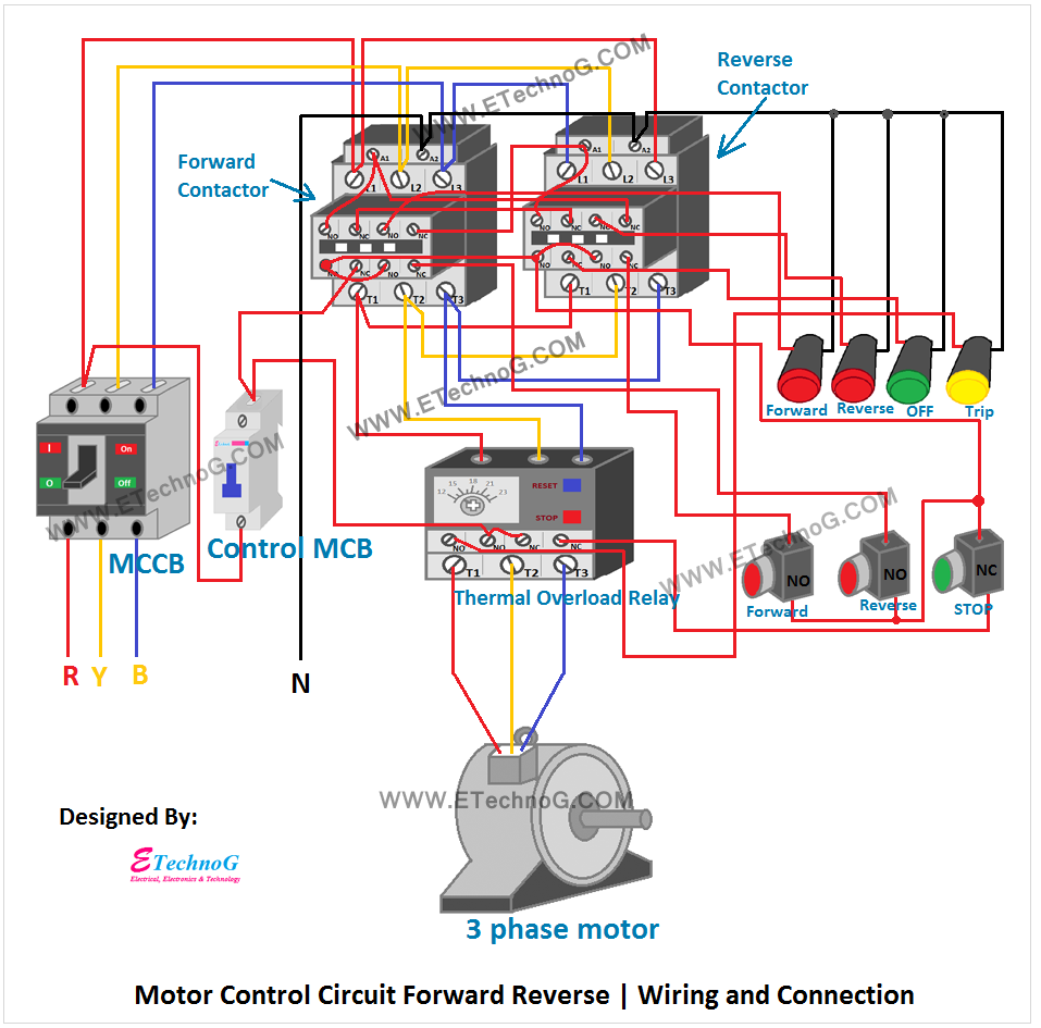
Motor control circuit forward reverseSchematics jog How overload heaters used to automatically shut the motor off ?Motor control wiring schematic diagrams.

Motor control circuits
How to construct wiring diagrams3 phase motor control circuit diagram Software reviews motor circuit tool machine cncCircuits instrumentation instrumentationtools.
Motor control circuit wiring instrumentation toolsMotor overload phase power control off heaters shut used automatically three circuits circuit heater instrumentationtools wiring tools protect fuses components Schematic and wiring diagrams in motor control.Circuits wiring pump2.

How to construct wiring diagrams
Motor control circuit wiring instrumentation tools .
.

Schematic and wiring diagrams in motor control. - YouTube

How Overload Heaters used to Automatically Shut the Motor OFF ? - Inst

CNC Machine Tool Book reviews and cnc software reviews by

How to Construct Wiring Diagrams - Industrial Motor Control Circuit

480 Volt Motor Wiring : Three Phase Motors The Wiring Connection And

Wiring diagram of the electric circuit for motor control. The circuit

Schematic vs. Wiring Diagrams – Basic Motor Control